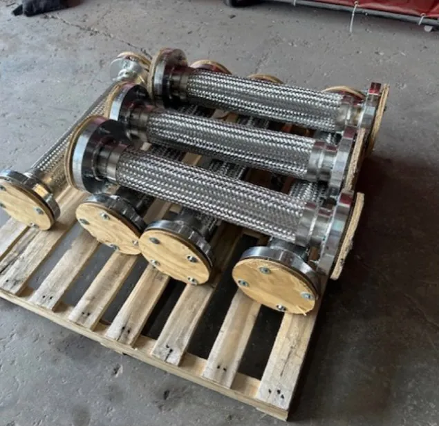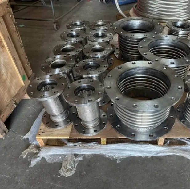
What is a metal expansion joint?
A metal expansion joint, also called a bellows expansion joint or compensator, is a flexible pressure-containing assembly installed in a pipe run or duct. Its working part is a bellows: a thin-wall tube, usually stainless steel, formed into a series of convolutions. The convolutions flex like an accordion, so the joint can absorb movement that would otherwise push on anchors, overstress welds or load pump and vessel nozzles.
Pipe grows when it heats and shrinks when it cools. A 100 ft run of carbon steel pipe heated from 70°F to 350°F grows by roughly 2.2 in. (12 × 100 ft × 6.5 × 10-6 in./in./°F × 280°F). A metal expansion joint takes that growth in a short, in-line package. It also isolates vibration from rotating equipment, takes up small installation misalignment and accommodates settlement or building movement.
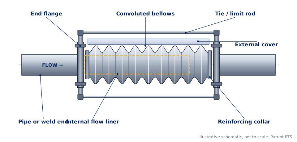
Parts of a metal expansion joint
| Part | What it does |
|---|---|
| Bellows | The flexible, pressure-containing element. Single-ply or multi-ply, with the number, height and pitch of convolutions set by the movement, pressure and cycle life needed. |
| End connections | Flanges (fixed or floating), weld ends, grooved ends or threaded ends that connect the joint to the piping. |
| Collars | Reinforce the bellows tangent where it attaches to the end fitting. |
| Internal liner | A sleeve welded at the inlet end that shields the convolutions from high-velocity, turbulent or erosive flow. It must be installed with the flow arrow pointing downstream. |
| External cover | A shroud that protects the bellows from weld spatter, dropped tools, insulation and abrasion. |
| Tie, limit and control rods | Tie rods restrain pressure thrust. Limit rods stop over-extension if an anchor fails. Control rods share movement between bellows. |
| Shipping bars | Temporary bars that hold the joint at its installed length during shipping and installation. They are painted to stand out and must be removed before the system operates. |
The movements a metal expansion joint absorbs
- Axial compression and extension: the joint shortens or lengthens along the pipe centerline, usually from thermal growth between two anchors.
- Lateral offset: the two ends move sideways relative to each other while staying parallel, common where a run turns a corner.
- Angular rotation: one end tilts relative to the other, in one plane (hinged) or any plane (gimbal).
- Torsion: twisting about the pipe axis. Bellows tolerate very little torsion, so piping design and installation must avoid it.
Movements are stated from the installed position: for example 1.5 in. compression and 0.25 in. extension. Joints may be precompressed or prestretched (cold set) at installation so the bellows works evenly about its neutral length.
Types of metal expansion joints
The joint type is chosen by the movement it must absorb and by whether it must contain its own pressure thrust. Each type has its own page with a diagram, uses and specifying notes.
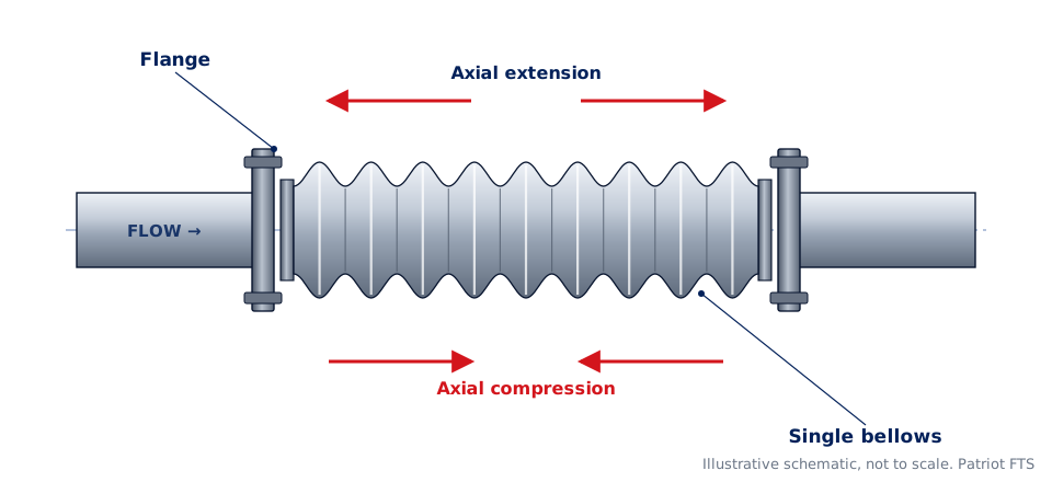 Single (axial)One bellows for axial growth between main anchors. Simplest and most compact.
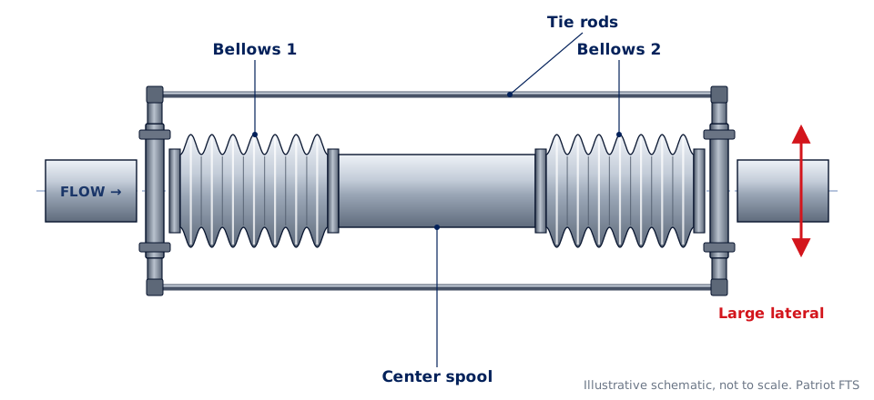 Universal and tied universalTwo bellows and a center spool for large lateral offset.
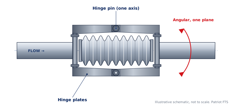 HingedAngular rotation in one plane, used in sets of two or three.
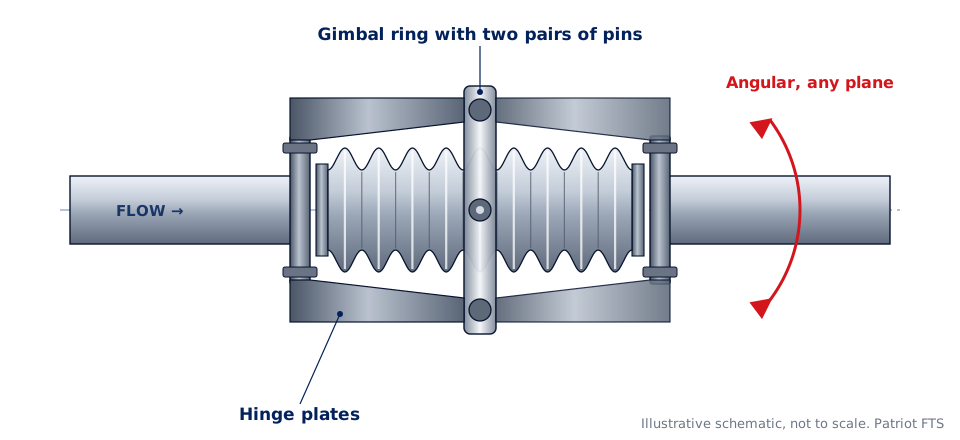 GimbalAngular rotation in any plane for three-dimensional piping.
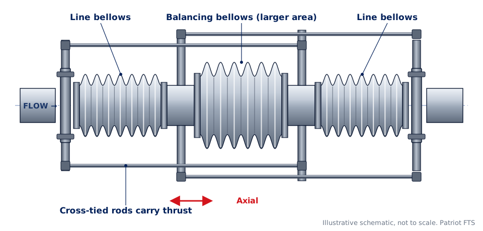 Pressure balancedAxial movement without pressure thrust on the anchors.
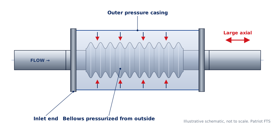 Externally pressurizedLong axial travel with the bellows pressurized from outside.
| Type | Axial | Lateral | Angular | Contains thrust |
|---|---|---|---|---|
| Single, unrestrained | Yes | Limited | Limited | No, needs main anchors |
| Single, tied | No | Yes | Limited | Yes, tie rods |
| Universal, tied | Thermal growth of spool only | Large | Limited | Yes, tie rods |
| Hinged | No | In sets | One plane | Yes, hinges |
| Gimbal | No | In sets | Any plane | Yes, gimbal ring |
| Pressure balanced | Yes | Some | Limited | Yes, balancing bellows |
| Externally pressurized | Large | No | No | No, needs main anchors |
Pressure thrust: why anchors matter
An unrestrained bellows acts like a piston. Internal pressure pushes the two ends of the joint apart with a force equal to the pressure times the bellows effective area. The effective area is based on the bellows mean diameter, which is larger than the pipe, so thrust is higher than pressure times the pipe bore.
Example: a bellows with a 7.6 in. mean diameter at 150 psig has Ae = 45.4 in.² and a thrust of about 6,800 lbf. At a 1.5 × hydrotest it is about 10,200 lbf.
Main anchors at each end of an unrestrained joint must resist that thrust plus the bellows spring force and guide friction. Restrained designs such as tied, universal, hinged, gimbal and pressure balanced joints carry thrust in their own hardware. The pressure thrust, anchors and guides guide works through the calculation step by step.
Anchors and pipe guides
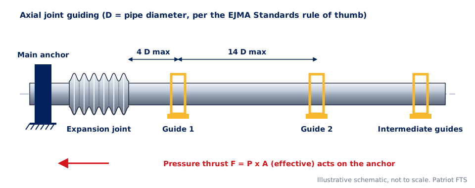
Axial joints make the line soft at one point, and pressure thrust tries to bow the pipe sideways. Pipe guides keep the movement straight into the bellows. The rule of thumb in the Expansion Joint Manufacturers Association (EJMA) Standards places the first guide within 4 pipe diameters of the joint and the second within 14 pipe diameters of the first. Intermediate guide spacing then depends on pressure and pipe size. The joint is usually located close to a main anchor. Your piping engineer sets final anchor and guide locations.
Bellows and fitting materials
Bellows are formed from thin sheet, so corrosion allowance is effectively zero. The bellows alloy is chosen for the media, temperature and chloride exposure, not just for pressure.
- 321 stainless steel: a common general-purpose bellows alloy, stabilized for elevated temperature service.
- 304 and 316L stainless steel: utility, HVAC, water and many process services. 316L adds resistance to pitting.
- Alloy 625 and other nickel alloys: chloride-bearing water, marine and severe corrosive service, and high temperature.
- End fittings: carbon steel or stainless steel flanges and pipe ends to match the piping.
See stainless steel expansion joints and bellows materials for a selection table.
Cycle life and what shortens it
A bellows is designed for a number of movement cycles. Each start-up and shutdown is one thermal cycle; vibration adds many small cycles. Cycle life drops quickly when a joint is pushed beyond its rated movement, twisted, installed out of alignment or exposed to corrosion. Under too much internal pressure a bellows can squirm: convolutions shift unevenly or the center bows out like a column. Correct guides, correct installed length and the right number of plies prevent it. ASME B31.3 Appendix X sets requirements for metallic bellows joints in process piping, including fatigue design and testing.
How to specify a metal expansion joint
- Size and ends: nominal pipe size and end connections, with flange class and facing.
- Design pressure and temperature, test pressure and media.
- Movements: axial compression and extension, lateral offset and angular rotation from the installed position, plus any vibration.
- Cycles: expected thermal cycles over the life of the joint.
- Face to face length available and any space limits.
- Options: liner, cover, tie or limit rods, and any code or project specification such as EJMA design or ASME B31.3 Appendix X.
- Materials: bellows alloy, flange and pipe material, and documentation such as MTRs and test reports.
Alternatives to a metal expansion joint
A bellows joint is not always the best answer. A flexible metal hose loop develops no pressure thrust, at the cost of more space. A rubber expansion joint damps noise and vibration at lower temperatures. For pump vibration alone, a flexible pump connector is often enough.
Patriot FTS supplies metal expansion joints alongside braided metal hose, U-loops, V-loops and pump connectors from Youngsville, Louisiana, so one quote can cover the whole movement problem. See metal expansion joints in Louisiana for local service.
From the Technical Reference
Tools for this job
Free tools you can use now, then email the result to Patriot FTS for a quote.
Ratings and dimensions are confirmed by Patriot FTS at quote.