Pressure thrust
A bellows has no hoop restraint in the axial direction, so internal pressure tries to stretch it. If the two ends are not tied together, that force goes into whatever holds the ends: the main anchors. The force is the pressure times the bellows effective area.
F = thrust (lbf), P = pressure (psig), Dm = bellows mean diameter (in.), halfway between the convolution root and crown diameters. Use the effective area on the joint data sheet when you have it.
Because Dm is larger than the pipe outside diameter, using the pipe size underestimates thrust. ASME B31.3 Appendix X requires restraint hardware to be designed for thrust at test pressure, and anchor design customarily checks the hydrotest case, often 1.5 times design pressure.
Worked example
| Step | Value |
|---|---|
| Line | 6 in. steam, 150 psig design |
| Bellows mean diameter (example data sheet) | 7.6 in. |
| Effective area | π × 7.6² ÷ 4 = 45.4 in.² |
| Thrust at design pressure | 150 × 45.4 = about 6,800 lbf |
| Thrust at 1.5 × hydrotest (225 psig) | about 10,200 lbf |
| Using pipe OD instead (6.625 in.) | about 5,200 lbf at design: 24% low |
Add the bellows spring force (spring rate times the movement) and the friction of the pipe guides and supports, and you have the axial load the main anchor must carry. Your piping engineer combines these with weight, wind and seismic loads.
Main and intermediate anchors
- Main anchors sit at each end of a straight run containing an unrestrained joint, at changes of direction, at branch connections and at closed ends. They resist full pressure thrust plus spring force and friction.
- Intermediate anchors divide a long run into sections, each with its own joint. They see the spring forces and friction but not pressure thrust, because the thrust from joints on either side balances.
- Restrained joints (tied, universal, hinged, gimbal and pressure balanced) carry thrust in their own hardware, so the adjacent anchors see much lower loads.
Pipe guides
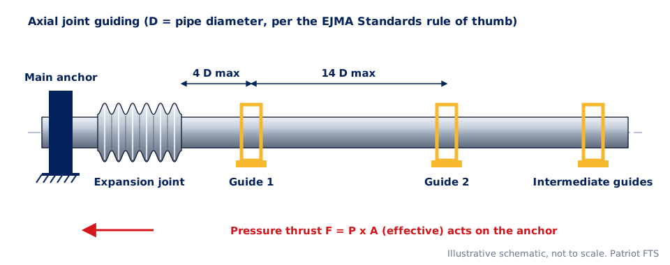
Pressure thrust makes the pipe beside an axial joint act like a column under compression. Guides keep it straight. The Expansion Joint Manufacturers Association (EJMA) Standards recommend:
- Locate the joint close to a main anchor.
- Place the first guide no more than 4 pipe diameters from the joint.
- Place the second guide no more than 14 pipe diameters from the first.
- Space intermediate guides by the EJMA chart or formula for the pressure, pipe size and pipe wall.
For a 6 in. line, that means the first guide within about 2 ft and the second within about 7 ft of the first. Guides must allow free axial movement; a pipe support that clamps the line is not a guide. Externally pressurized joints and lateral or angular systems have their own guiding rules from the joint data sheet.
Estimating thermal growth
ΔL = growth (in.), L = length between anchors (ft), α = mean coefficient of expansion (in./in./°F), ΔT = temperature change (°F).
Typical mean coefficients near this range: carbon steel about 6.5 × 10⁻⁶, austenitic stainless about 9.5 × 10⁻⁶ in./in./°F. Example: 100 ft of carbon steel from 70°F to 350°F grows about 2.2 in.; the same run in stainless grows about 3.2 in. Use the code tables for design values. The expansion loop sizer runs this calculation for loops.
Common mistakes
- Using pipe size instead of the bellows effective area for thrust.
- Designing anchors for operating pressure only and forgetting the hydrotest.
- Placing the first guide too far from the joint, or using hangers that do not guide.
- Removing shipping bars before anchors are in place.
- Using an axial joint to take lateral offset it was not designed for.