
FTS-TD-106REV A · NOVEMBER 2026
Expansion Loop Sizing and Movement
Thermal growth · movement · loop selection · installation
How to estimate pipe movement and give Patriot FTS what we need to size a flexible expansion loop. We confirm final dimensions, pressure rating and movement capacity during application review.
Thermal growth
ΔL = α × L × ΔT
ΔL = change in length, in
α = coefficient of thermal expansion, in/in/°F
L = pipe length between anchors, in
ΔT = temperature change, °F
ΔL = change in length, in
α = coefficient of thermal expansion, in/in/°F
L = pipe length between anchors, in
ΔT = temperature change, °F
| Pipe material | α, ×10−6 in/in/°F |
|---|---|
| Carbon steel | 6.5 |
| 304 stainless | 9.6 |
| Copper | 9.3 |
| Temperature | Carbon steel | 304 stainless | Copper |
|---|---|---|---|
| 100°F | 0.76 | 1.12 | 1.13 |
| 200°F | 1.52 | 2.24 | 2.30 |
| 300°F | 2.35 | 3.40 | 3.46 |
| 400°F | 3.23 | 4.59 | 4.87 |
Total expansion in inches per 100 ft, measured from 0°F. For growth between two temperatures, subtract the lower row from the higher and interpolate. Stainless and copper grow roughly 40–50% more than carbon steel.
Worked example
100 ft of carbon steel, installed at 70°F, operating at 250°F: L = 1,200 in, ΔT = 180°F, ΔL = 0.0000065 × 1,200 × 180 ≈ 1.40 in. The same run in 304 stainless grows about 2.07 in, and in copper about 2.01 in. Use the full range: from the lowest temperature (installation or winter shutdown) to the highest operating or upset temperature.
100 ft of carbon steel, installed at 70°F, operating at 250°F: L = 1,200 in, ΔT = 180°F, ΔL = 0.0000065 × 1,200 × 180 ≈ 1.40 in. The same run in 304 stainless grows about 2.07 in, and in copper about 2.01 in. Use the full range: from the lowest temperature (installation or winter shutdown) to the highest operating or upset temperature.
Add other movement
| Source | How to state it |
|---|---|
| Thermal | Calculated ΔL along the run, from the formula above |
| Seismic | From the engineer of record, ± in each axis |
| Building settlement / structural joints | Expected settlement and joint movement where the pipe crosses |
| Equipment | Tank settlement, nozzle growth or equipment travel |
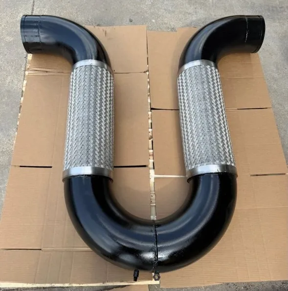
State each movement by direction (X, Y, Z) and whether it is total or ±. A flexible U-loop can take movement in all three directions at once.
Choosing a flexible connector
| Type | Geometry | Typical use |
|---|---|---|
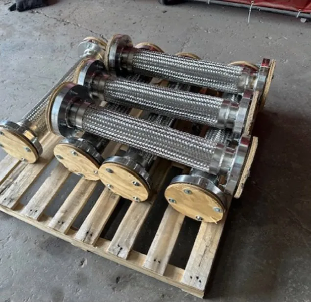
| U-loop | Two parallel hose legs and a 180° return, set perpendicular to the run | Thermal growth, settlement and seismic movement in X, Y and Z |
| V-loop | Two hose legs in a V meeting at a return | Risers and tight layouts; shorter offset, longer footprint, more return travel |
| Dog-leg offset | Hose legs joined by elbows to make an offset | Movement at changes in direction and equipment connections |
| Metal expansion joint | In-line bellows | Axial movement in a straight run; needs anchors and guides sized for pressure thrust |
Flexible loops develop no pressure thrust, so anchors mainly resist friction and the force to flex the loop. Your piping engineer sets anchor locations, loads and guides. Your piping engineer still sets anchor locations and loads.
Placement and anchors
- A loop absorbs the growth of the pipe between two anchors. It can sit anywhere in that run as long as the return is free to move so each leg flexes equally.
- Guides keep the pipe moving along its axis toward the loop.
- Larger loops need the 180° return supported by a hanger that lets it travel, such as a spring or swivel hanger.
- In horizontal installations, support the arms so the hose does not sag.
- On a V-loop the return moves more than on a U-loop: keep clearance around it and do not clamp it rigidly.
Installation rules
- No torsion. Align flanges and threads without twisting the hose; use two wrenches on threaded ends.
- No axial compression or extension. Do not push or pull a hose to fit a gap. Hose grows about 1–2% in length under pressure.
- Respect bend radius. Flexing service uses the dynamic radius, often about twice the static value (FTS-TD-101).
- Neutral zone. Allow about 2 in of straight hose at each fitting before a bend.
- Test before covering. Pressure test and check for leaks before insulating.
Standard construction
| Component | Standard | Options |
|---|---|---|
| Hose | 316 stainless annular corrugated | Other alloys for corrosive service (FTS-TD-103) |
| Braid | Stainless, single braid | Double braid for higher pressure or steam |
| Return | 180° return fitting | Support lug, drain or vent on request |
| Ends | Flanged, grooved, weld or threaded | Custom ends to your drawing |
| Bronze / copper | Bronze hose loops | Compatible water and HVAC systems |
Loop sizing data Fill in, print and send with your drawing
| Project / tag | Quantity | ||
| Nominal pipe size / schedule | Pipe and fitting material | ||
| Fluid or gas | Flammable / hazardous? | ||
| Operating / design pressure | Test pressure | ||
| Min. / max. temperature | Installation temperature | ||
| Run length between anchors | Calculated thermal ΔL | ||
| Movement X / Y / Z | Total or ±? | ||
| End type and pressure class | Orientation (horizontal, vertical, riser) | ||
| Available L / W / H | Piping code / listings required |
Send it to us
Email this sheet, a drawing or field sketch and photos to sales@patriotfts.com, or use the fillable Hose Assembly Specification Worksheet (FTS-TD-105). Every Patriot FTS loop is pressure tested and tagged by NDT Level II personnel before it ships.
Email this sheet, a drawing or field sketch and photos to sales@patriotfts.com, or use the fillable Hose Assembly Specification Worksheet (FTS-TD-105). Every Patriot FTS loop is pressure tested and tagged by NDT Level II personnel before it ships.